про TPLink:
(основную ссылку потерял, найду обновлю. кратко так)
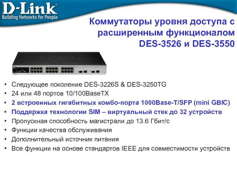
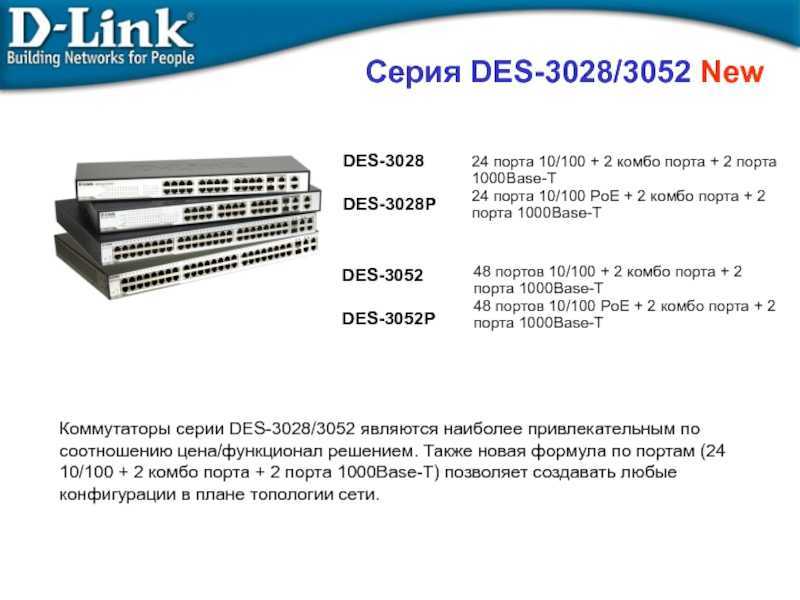
На официальном веб-сайте TP-LINKпредставлены различные серии коммутаторов TP-LINK, включая управляемые коммутаторы 2/3 уровня, Smart-коммутаторы, коммутаторы EasySmartи неуправляемые коммутаторы. В данной статье будет дано кратное описание функций и способов применения коммутаторов данных серий.
Неуправляемый коммутатор (UnmanagedSwitch)
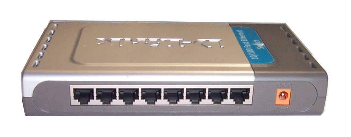
Вы не можете настраивать неуправляемые коммутаторы, потому что они не обладают каким-либо интерфейсом настройки, а также дополнительными функциями. Данные маршрутизаторы работают по принципу Plug-and-Play, поэтому всё, что от вас потребуется – это подключить напрямую к коммутатору ваш компьютер и прочие сетевые устройства. Таким образом, если вы не нуждаетесь в каких-либо функциях 2 уровня, и вам просто необходимо увеличить количество портов Ethernet, то неуправляемые коммутаторы – это то, что вам нужно.
Коммутатор Easy Smart (Easy Smart Switch)
Вы можете использовать утилиту настройки или веб-интерфейс (веб-интерфейс доступен только для TL-SG1016DEи TL-SG1024DE) для управления коммутатором EasySmartи настройки основных параметров, таких как VLAN, QoS, а также нескольких функций L2, таких как LAG, IGMPSnooping и зеркалирование порта. Если вам не требуется коммутатор для каких-либо продвинутых сценариев применения, то коммутатор EasySmart станет для вас идеальным выбором. Наилучшим применением коммутатора EasySmartбудет являться дом, домашний и малый офис, а также небольшое предприятие.
Smart-коммутатор (Smart Switch)
Smart-коммутаторы могут управляться через веб-интерфейс, Telnet, SSHи SNMP. Они поддерживают гораздо больше функций L2 и обладают более эффективной функцией приоритезации трафика (QoS) по сравнению с коммутаторами EasySmart. Smart-коммутаторы поддерживают гораздо больше продвинутых функций, таких как ACL и протокол SpanningTree. Если вам необходимо более доступное решение для небольшой компании, то Smart-коммутатор окажется незаменимым.
Управляемый коммутатор 2 уровня (L2 ManagedSwitch)
Управляемые коммутаторы 2 уровня обладают консольным портом для интерфейса командной строки (CLI), а также всеми дополнительным функциями Smart-коммутаторов. Помимо этого коммутаторы 2 уровня обладают функциями VLANи Multicast, а также кластеризацией для логического стекирования и функциями сетевой безопасности, включая 802.1X и привязку по IPи MAC-адресу. Таким образом, вы можете использовать управляемые коммутаторы 2 уровня для создания масштабируемой и доступной сети, а также для создания небольшой сети доступа для Интернет-провайдеров.
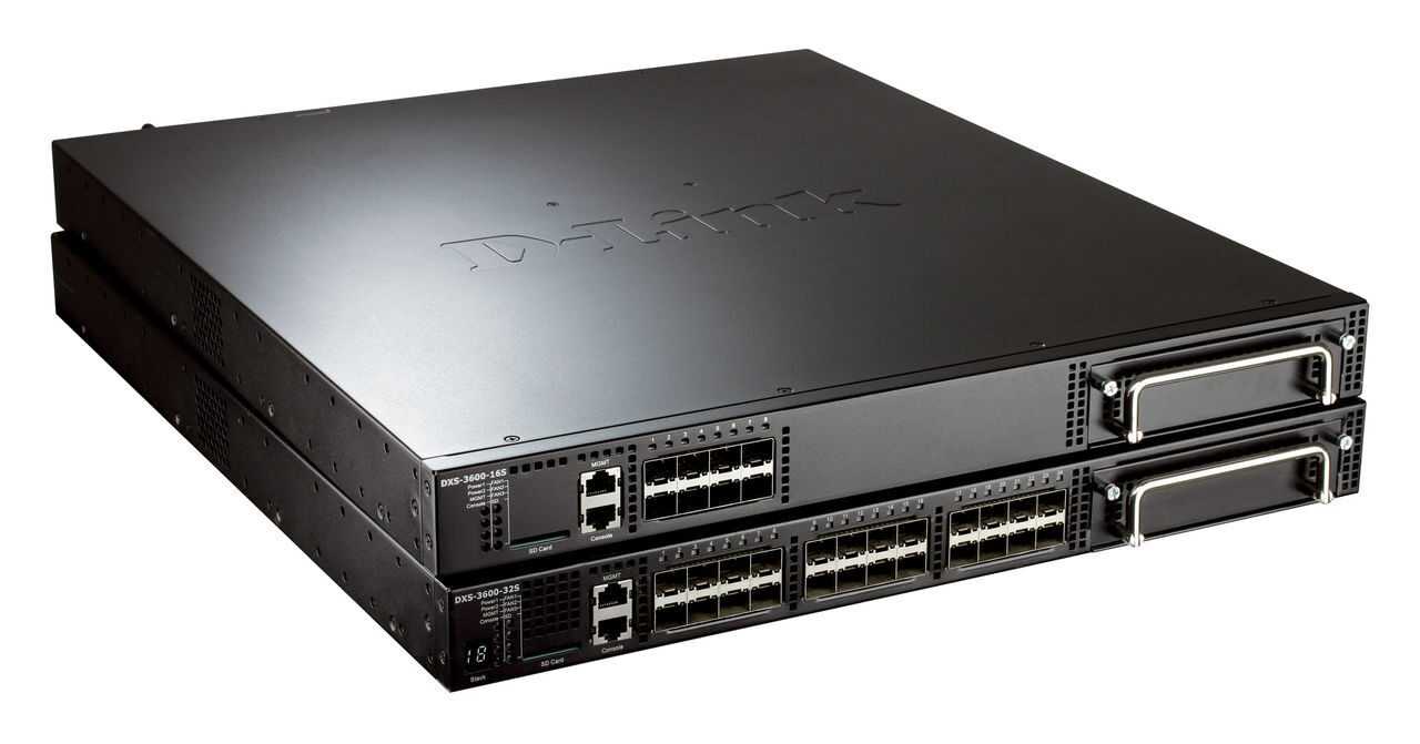
Управляемый коммутатор 3 уровня (L3 ManagedSwitch)
Коммутаторы 2 уровня могут работать только на втором уровне модели OSI – канальном (datalink). Но коммутаторы 3 уровня обладают некоторыми функциями 3 уровня, также как и традиционные маршрутизаторы, а именно: статической маршрутизацией, протоколами маршрутизации OSPF и ECMP, протоколом многоадресной маршрутизации, а также DHCP relay.
По сравнению с традиционными маршрутизаторами коммутаторы 3 уровня обладают более низкой ценой, но лучшей производительностью в отношении скорости маршрутизации пакетов, поскольку коммутаторы 3 уровня маршрутизируют пакеты, используя специализированную интегральную схему (ASIC) вместо процессора. После того, как коммутатор определил IP-адрес, он будет пересылать пакеты, на уровне производительности коммутатора. Основной способ применения коммутаторов 3 уровня – это уровень ядра в сетях средних предприятий, обеспечивающий производительность на уровне коммутатора в маршрутизации пакетов.
Так же у TP-Link есть симулятор, где можно ознакомиться с интерфейсом:
Configuring Default Gateways
The supervisor engine sends IP packets that are destined for other IP subnets to the default gateway (typically, a router interface in the same network or subnet as the switch IP address). The switch does not use the IP routing table to forward traffic from connected devices; the switch forwards only IP traffic that is generated by the switch (for example, Telnet, TFTP, and ping).
Note In some cases, you might want to configure static IP routes in addition to default gateways. For information on configuring static routes, see the .
You can define up to three default IP gateways. Use the primary keyword to make a gateway the primary gateway. If you do not specify a primary default gateway, the first gateway that is configured is the primary gateway. If more than one gateway is designated as primary, the last primary gateway that is configured is the primary default gateway.
The switch sends all off-network IP traffic to the primary default gateway. If connectivity to the primary gateway is lost, the switch attempts to use the backup gateways in the order that they were configured. The switch sends periodic ping messages to determine whether each default gateway is up or down. If connectivity to the primary gateway is restored, the switch resumes sending traffic to the primary gateway.
If both the in-band (sc0) and management Ethernet (me1) interfaces are configured when you specify default gateways, then the switch software automatically determines through which interface each default gateway can be reached.
To specify one or more default gateways, perform this task in privileged mode:
|
Task |
Command |
|
|---|---|---|
|
Step 1 |
Configure a default IP gateway address for the switch. |
set ip route default gateway [primary] |
|
Step 2 |
(Optional) Configure additional default gateways for the switch. |
set ip route default gateway [primary] |
|
Step 3 |
Verify that the default gateways appear correctly in the IP routing table. |
show ip route |
To remove default gateway entries, perform one of these tasks in privileged mode:
|
Task |
Command |
|---|---|
|
Clear an individual default gateway entry. |
clear ip route default gateway |
|
Clear all default gateways and static routes. |
clear ip route all |
This example shows how to configure three default gateways on the switch and how to verify the default gateway configuration:
Console> (enable) set ip route default 10.1.1.10
Route added.
Console> (enable) set ip route default 10.1.1.20
Route added.
Console> (enable) set ip route default 10.1.1.1 primary
Route added.
Console> (enable) show ip route
Fragmentation Redirect Unreachable
------------- -------- -----------
enabled enabled enabled
The primary gateway: 10.1.1.1
Destination Gateway RouteMask Flags Use Interface
--------------- --------------- ---------- ----- -------- ---------
default 10.1.1.1 0x0 UG 6 sc0
default 10.1.1.20 0x0 G 0 sc0
default 10.1.1.10 0x0 G 0 sc0
10.0.0.0 10.1.1.100 0xff000000 U 75 sc0
default default 0xff000000 UH 0 sl0
Console> (enable)
This example shows how to configure two default gateways on a Catalyst 4500 series, Catalyst 2948G, Catalyst 2948G-GE-TX, or Catalyst 2980G switch, with one default gateway reachable through the sc0 interface and one reachable through the me1 interface:
Console> (enable) show interface
sl0: flags=50<DOWN,POINTOPOINT,RUNNING>
slip 0.0.0.0 dest 0.0.0.0
sc0: flags=63<UP,BROADCAST,RUNNING>
vlan 5 inet 172.20.52.38 netmask 255.255.255.240 broadcast 172.20.52.47
me1: flags=63<UP,BROADCAST,RUNNING>
inet 10.1.1.100 netmask 255.255.255.0 broadcast 10.1.1.255
Console> (enable) set ip route default 172.20.52.33
Route added.
Console> (enable) set ip route default 10.1.1.1
Route added.
Console> (enable) show ip route
Fragmentation Redirect Unreachable
------------- -------- -----------
enabled enabled enabled
The primary gateway: 172.20.52.33
Destination Gateway RouteMask Flags Use Interface
--------------- --------------- ---------- ----- -------- ---------
default 10.1.1.1 0x0 G 0 me1
default 172.20.52.33 0x0 UG 12 sc0
172.20.52.32 4000-2 0xfffffff0 U 180 sc0
10.1.1.0 10.1.1.100 0xffffff00 U 22 me1
Console> (enable)
Q-in-Q
« role uni » означает, что взаимодействие по этим портам будет осуществляться между пользователем и граничным коммутатором провайдера.
« role nni » означает, что этот порт взаимодействует с сетью провайдера или другим граничным коммутатором.
«vlan_translation» данные правила ассоциирует C-VID с SP-VID.
«missdrop enable» означает, что добавление внешнего тега(SP-VLAN) будет осуществляться только согласно правилам vlan_translation.
«missdrop disable» означает, что добавление внешнего тега(SP-VLAN) будет осуществляться согласно правилам vlan_translation,
а к трафику не попавшему под правила vlan_translation будет добавляться внешний тег(SP-VLAN) равный PVID
порта, т.е. SP-VID = PVID.
«use_inner_priority enable» означает, что коммутатор будет использовать приоритет 802.1p тега C-VLAN в теге SP-VLAN.
«outer_tpid» означает, что коммутатор будет задавать TPID для внешнего тега(SP-VLAN) равный заданному значению.
Согласно стандарту IEEE 802.1ad TPID равен 0x88A8 для Q-in-Q пакетов. У Cisco TPID равен 0x9100. Сейчас на всех современных коммутаторах можно задать любой TPID для совместимости оборудования разных вендоров, например: можно задать TPID равный 0x8100, как у обычного IEEE 802.1q VLAN, в случае, если необходимо пропустить трафик с двумя тегами через оборудование с поддержкой IEEE 802.1q, но без поддержки Q-in-Q. 
Фильтры для свичей доступа
Настроить port security, запретив более одного mac адреса на порту (таким образом мы боремся с нежелательной и потенциально опасной ситуацией, когда клиент подключает в сеть провайдера не маршрутизатор, а коммутатор, сливая бродакстовый домен своей домашней сети с бродкастовым доменом провайдера)
config port_security ports 1-8 admin_state enable max_learning_addr 1 lock_address_mode deleteontimeout
Запретить STP на клиентских портах, чтобы пользователи не могли гадить в сеть провайдера BPDU пакетами
config stp version rstp
config stp ports 1-8 fbpdu disable state disable
Настроить loopback detection, чтобы 1) глючные сетевые карточки, которые отражают пакеты обратно и 2) пользователи, создавшие в своей квартире кольца на втором уровне не мешали работе сети
enable loopdetect
config loopdetect recover_timer 1800
config loopdetect interval 10
config loopdetect ports 1-8 state enable
config loopdetect ports 9-10 state disable
Создать acl, который запретит прохождение не PPPoE пакетов в USER vlan’е (блокируем DHCP, IP, ARP и все остальные ненужные протоколы, которые позволят пользователям общаться напрямую между собой, игнорируя PPPoE сервер).
create access_profile ethernet vlan 0xFFF ethernet_type profile_id 1
config access_profile profile_id 1 add access_id 1 ethernet vlan USER ethernet_type 0x8863 port 1-10 permit
config access_profile profile_id 1 add access_id 2 ethernet vlan USER ethernet_type 0x8864 port 1-10 permit
config access_profile profile_id 1 add access_id 3 ethernet vlan USER port 1-10 deny
Создать ACL, который запретит PPPoE PADO пакеты с клиентских портов (блокируем поддельные PPPoE сервера).
create access_profile packet_content_mask offset1 l2 0 0xFFFF offset2 l3 0 0xFF profile_id 2
config access_profile profile_id 2 add access_id 1 packet_content offset1 0x8863 offset2 0x0007 port 1-8 deny
И, наконец, включить STORM Control для борьбы с бродкастовыми и мультикастовыми флудами. Может показаться, что мы уже решили эту проблему, запретив не PPPoE трафик, однако есть но. В PPPoE первый запрос (на поиск PPPoE сервера) отсылается бродкастом, и если оборудование клиента в силу глюка, вируса или иных причин, посылает такие запросы интенсивно, это вполне может вывести сеть из строя.
config traffic control 1-8 broadcast enable multicast enable action drop threshold 64 countdown 5 time_interval 5
ACL для DES-3200-52
create access_profile profile_id 1 profile_name microsoft ip tcp dst_port_mask 0xFFFF
config access_profile profile_id 1 add access_id auto_assign ip tcp dst_port 135 port 1-48 deny
config access_profile profile_id 1 add access_id auto_assign ip tcp dst_port 139 port 1-48 deny
config access_profile profile_id 1 add access_id auto_assign ip tcp dst_port 369 port 1-48 deny
config access_profile profile_id 1 add access_id auto_assign ip tcp dst_port 445 port 1-48 deny

create access_profile profile_id 2 profile_name microsoft_udp ip udp dst_port_mask 0xFFFF
config access_profile profile_id 2 add access_id auto_assign ip udp dst_port 137 port 1-48 deny
config access_profile profile_id 2 add access_id auto_assign ip udp dst_port 138 port 1-48 deny
PPPoE только на Uplink
PPPoE — концентратор подключён к порту 26 коммутатора DES-3526, клиенты подключены к портам 1-25, MAC-адрес концентратора — 00-13-5F-AA-BB-CC.
Настройки DES-3526:
1. Создаём профиль ACL для разрешения PPPoE-пакетов от концентратора клиентам
create access-profile ethernet source_mac FF-FF-FF-FF-FF-FF ethernet_type profile 1
2. Разрешаем PPPoE-session-пакеты от концентратора клиентам
config access-profile 1 add access_id 100 ethernet source_mac 00-13-5F-AA-BB-CC ethernet_type 0x8863 port 26 permit
3. Разрешаем PPPoE-data-пакеты от концентратора клиентам
config access-profile 1 add access_id 200 ethernet source_mac 00-13-5F-AA-BB-CC ethernet_type 0x8864 port 26 permit
4. Создаём профиль ACL для разрешения PPPoE-пакетов от клиентов концентратору или серверу
create access-profile ethernet destination_mac FF-FF-FF-FF-FF-FF ethernet_type profile 2
5. Разрешаем широковещательные PPPoE-session PADI пакеты от клиентов
config access-profile 2 add access_id 100 ethernet destination FF-FF-FF-FF-FF-FF ethernet_type 0x8863 port 1-25 permit
6. Разрешаем PPPoE-session пакеты от клиентов к серверу
config access-profile 2 add access_id 200 ethernet destination 00-13-5F-AA-BB-CC ethernet_type 0x8863 port 1-25 permit
7. Разрешаем PPPoE-session пакеты от клиентов к серверу
config access-profile 2 add access_id 300 ethernet destination 00-13-5F-AA-BB-CC ethernet_type 0x8864 port 1-25 permit
8. Создаём профиль ACL для запрещения всех остальных PPPoE-пакетов
create access-profile ethernet ethernet_type profile 3
9. Запрещаем все остальные PPPoE пакеты
config access-profile 3 add access_id 100 ethernet ethernet_type 0x8863 port 1-26 deny
config access-profile 3 add access_id 200 ethernet ethernet_type 0x8864 port 1-26 deny
Основные команды для работы с коммутаторами D-Link серии DES и DXS
Просмотр основных характеристик коммутаторов dlink
show switch
Просмотр загрузки процессора (CPU)
show utilization cpu
Работа с конфигурацией
Просмотр текущей конфигурации
show config current_config
Просмотр конфигурации в nvram
show config config_in_nvram
Сохранение текущей конфигурации
save
Сброс к заводским настройкам
reset system
Выгрузка конфига на TFTP:
Обычный упр. свич
upload cfg_toTFTP 10.10.10.5 dest_file conf.cfg
Смарт свич
upload cfg_toTFTP 10.10.10.5 config.txt config_id 1
Настройка ip маски и шлюза
Настройка IP адреса и сетевой маски.
config ipif ipaddress [ip-адрес/маска]
Пример:
config ipif SYS ipaddress 192.168.5.10/24
Просмотр интерфейсов управления.
show ipif
Задание шлюза по умолчанию.
create iproute default
Пример:
create iproute default 192.168.5.1
Просмотра маршрута по умолчанию.
show iproute
Удаление маршрута по умолчанию.
delete iproute default
Настройка VLAN на коммутаторах dlink
Просмотр всех созданных vlan.
show vlan
Создание vlan.
create vlan tag
Пример:
create vlan USER tag 813
Добавление vlan на порты.
config vlan add
Пример:
config vlan USERTAG add untagged 1-3,5
config vlan USERUNTAG add tagged 8,10
config vlan USER add forbidden 9
В первом случае добавляется нетегированная (untagged) vlan на порты 1,2,3,5.
Во втором случае добавляется тегированная (tagged) vlan на порты 8,10.
В третьем случае запрещается прохождение vlan на 9-ом порту.
![Cisco enterprise network compute system switch command reference - ip addressing commands [cisco enterprise nfv infrastructure software] - cisco](https://robotrackkursk.ru/wp-content/uploads/e/5/c/e5c5b2a0e63aa148003c80b8358a0050.jpeg)
Настройка vlan управления коммутатора:
config ipif vlan ipaddress [ip-адрес/маска] state enable
Пример:
config ipif SYS vlan management ipaddress 192.168.2.40/24 state enable
Удаление default vlan со всех портов.
config vlan default delete 1-26
Настройка пользователей на коммутаторах dlink
Настройка имени пользователя и пароля.
create account
Пример:
create account admin admin
Enter a case-sensitive new password:********
Enter the new password again for confirmation:********
Просмотр учетной записи.
show account
Cменить пароль существующему пользователю.
config account
Пример:
config account admin
Enter a old password:********
Enter a case-sensitive new password:********
Enter the new password again for confirmation:********
Просмотр mac и arp таблиц
Просмотр таблицы mac-адресов.
show fdb
Просмотр таблицы mac-адресов для определенного порта.
show fdb port
Пример:
show fdb port 5
Просмотр arp табицы.
show arpentry
Просмотр диагностической информации по портам
Просмотр режимов работы портов (Speed, Duplex, FlowCtrl).
show ports
Просмотр ошибок на портe.
show error ports
Пример:
show error ports 3
Просмотр статистики по всем портам.
show utilization ports
Посмотреть инфу о SFP модуле
show ddm ports 10 status
Установка комментария на порт
config ports description
Пример:
config ports 10 description my-server
размер комментария может содержать до 32 символов и не должен содержать пробелы.
Preparing to Configure the IP Address and Default Gateway
Before you configure the switch IP address and default gateway, obtain the following information, as appropriate:
•IP address for the switch (sc0 and me1 interfaces only)
•Subnet mask/number of subnet bits (sc0 and me1 interfaces only)
•(Optional) Broadcast address (sc0 and me1 interfaces only)
•VLAN membership (sc0 interface only)
•SLIP and SLIP destination addresses (sl0 interface only)
•Interface connection type:
–In-band (sc0) interface
Configure this interface when assigning an IP address, subnet mask, and VLAN to the in-band management interface on the switch.
–Out-of-band management Ethernet (me1) interface
Configure this interface when assigning an IP address and subnet mask to the out-of-band management Ethernet interface on the switch.
–SLIP (sl0) interface
Configure this interface when setting up a point-to-point SLIP connection between a terminal and the switch.
Renewing and Releasing a DHCP-Assigned IP Address
If you are using DHCP for IP address assignment, you can perform either of these tasks:
•Renew—Renew the lease on a DHCP-assigned IP address.
•Release—Release the lease on a DHCP-assigned IP address.
To renew or release a DHCP-assigned IP address on the in-band (sc0) management interface, perform one of these tasks in privileged mode:
|
Task |
Command |
|---|---|
|
Renew the lease on a DHCP-assigned IP address. |
set interface sc0 dhcp renew |
|
Release the lease on a DHCP-assigned IP address. |
set interface sc0 dhcp release |
This example shows how to renew the lease on a DHCP-assigned IP address:
Console> (enable) set interface sc0 dhcp renew
Renewing IP address...
Console> (enable) Sending DHCP packet with address: 00:90:0c:5a:8f:ff
<...output truncated...>
This example shows how to release the lease on a DHCP-assigned IP address:
Console> (enable) set interface sc0 dhcp release
Releasing IP address...
Console> (enable) Sending DHCP packet with address: 00:90:0c:5a:8f:ff
Done
Console> (enable)
Первоначальная настройка
Прибиваем предыдущую конфигурацию
reset system
Заливаем актуальный минимум
create vlan manage tag 10
config vlan manage add tagged 49-52
config vlan manage add forbidden 1-48
create iproute default 10.10.0.1
config ipif System vlan manage ipaddress 10.10.24.254/16 state enable
enable sntp
config time_zone operator + hour 3 min 0
config sntp primary 10.10.0.25 secondary 0.0.0.0 poll-interval 720
config log_save_timing on_demand
enable syslog
config system_severity trap information
config system_severity log information
create syslog host 1 ipaddress 10.10.0.25 severity debug facility local0 udp_port 514 state enable
enable jumbo_frame
enable qinq
config qinq ports 1-52 role nni missdrop disable outer_tpid 0x8100
save all
Апгрейд прошивки за два подхода (save после каждого обязателен!)
download firmware_fromTFTP 10.10.0.25 src_file DES3200R_4.38.B000.had
save
reboot

download firmware_fromTFTP 10.10.0.25 src_file DES3200R_4.44.B001.had
save
reboot
Understanding How Automatic IP Configuration Works
These sections describe how the switch can obtain its IP configuration automatically:
•
•
•
Automatic IP Configuration Overview
The switch can obtain its IP configuration automatically using one of the following protocols:
•Dynamic Host Configuration Protocol (DHCP)
•Reverse Address Resolution Protocol (RARP)
The switch makes DHCP and RARP requests only if the sc0 interface IP address is set to 0.0.0.0 when the switch boots up. This address is the default for a new switch or a switch whose configuration file has been cleared using the clear config all command. DHCP and RARP requests are only broadcast out the sc0 interface.
Note If the CONFIG_FILE environment variable is set, all configuration files are processed before the switch determines whether to broadcast DHCP and RARP requests. For more information about the CONFIG_FILE environment variable, see
If both the sc0 and me1 interfaces are unconfigured (IP address 0.0.0.0), the me1 interface is brought down to allow the switch to broadcast requests on the sc0 interface. If the me1 interface is configured and the sc0 interface is not, requests are not sent. Similarly, if the sc0 interface is not configured but the interface is configured down, requests are not sent.
Understanding DHCP
In software release 5.2 and later releases, the switch can obtain an IP address and other IP configuration information using DHCP.
There are three methods for obtaining an IP address from the DHCP server:
•Manual allocation—The network administrator maps the switch MAC address to an IP address at the DHCP server.
•Automatic allocation—The switch obtains an IP address when it first contacts the DHCP server. The address is permanently assigned to the switch.
•Dynamic allocation—The switch obtains a «leased» IP address for a specified period of time. The IP address is revoked at the end of this period, and the switch surrenders the address. The switch must request another IP address.
In addition to the sc0 interface IP address, the switch can obtain the subnet mask, broadcast address, default gateway address, and other information. DHCP-learned values are not used if user-configured values are present.
The switch broadcasts a DHCPDISCOVER message 1 to 10 seconds after all of the switch ports are online. The switch always requests an infinite lease time in the DHCPDISCOVER message.
If a DHCP or Bootstrap Protocol (BOOTP) server responds to the request, the switch takes appropriate action. If a DHCPOFFER message is received from a DCHP server, the switch processes all the supported options that are contained in the message. shows the supported DHCP options. Other options that are specified in the DHCPOFFER message are ignored.
Table 3-1 Supported DHCP Options
Code
Option
1
Subnet mask
2
Time offset
3
Router
6
Domain name server
12
Host name
15
Domain name
28
Broadcast address
33
Static route
42
NTP servers
51
IP address lease time
52
Option overload
61
Client-identifier
66
TFTP server name
If a BOOTP response is received from a BOOTP server, the switch sets the in-band (sc0) interface IP address to the address that is specified in the BOOTP response.
If no DHCPOFFER message or BOOTP response is received in reply, the switch rebroadcasts the request using an exponential backoff algorithm (the amount of time between requests increases exponentially). If no response is received after 10 minutes, the sc0 interface IP address remains set to 0.0.0.0 (provided that RARP requests fail as well).
If you reset or power cycle a switch with a DHCP- or BOOTP-obtained IP address, the information learned from DHCP or BOOTP is retained. At boot up, the switch attempts to renew the lease on the IP address. If no reply is received, the switch retains the current IP address.
Understanding RARP
With RARP, you map the switch MAC address to an IP address on the RARP server. The switch retrieves its IP address from the server automatically when it boots up.
The switch broadcasts ten RARP requests after all of the switch ports are online. If a response is received, the switch sets the in-band (sc0) interface IP address to the address that is specified in the RARP response.
If no reply is received, the sc0 interface IP address remains set to 0.0.0.0 (provided that DHCP requests fail as well).
If you reset or power cycle a switch with a RARP-obtained IP address, the information that is learned from RARP is retained.
Configuring the SLIP (sl0) Interface on the Console Port
Use the SLIP (sl0) interface for point-to-point SLIP connections between the switch and an IP host.
Caution
You
must use the console port for the SLIP connection. When the SLIP connection is enabled and SLIP is attached on the console port, an EIA/TIA-232 terminal cannot connect through the console port. If you are connected to the switch CLI through the console port and you enter the
slip attach command, you will lose the console port connection. Use Telnet to access the switch, enter privileged mode, and enter the
slip detach command to restore the console port connection.
To enable and attach SLIP on the console port, perform this task:
|
Task |
Command |
|
|---|---|---|
|
Step 1 |
Access the switch from a remote host with Telnet. |
telnet {host_name | ip_addr} |
|
Step 2 |
Enter privileged mode on the switch. |
enable |
|
Step 3 |
Set the console port SLIP address and the destination address of the attached host. |
set interface sl0 slip_addr dest_addr |
|
Step 4 |
Verify the SLIP interface configuration. |
show interface |
|
Step 5 |
Enable SLIP for the console port. |
slip attach |
To disable SLIP on the console port, perform this task:
|
Task |
Command |
|
|---|---|---|
|
Step 1 |
Access the switch from a remote host with Telnet. |
telnet {host_name | ip_addr} |
|
Step 2 |
Enter privileged mode on the switch. |
enable |
|
Step 3 |
Disable SLIP for the console port. |
slip detach |
This example shows how to configure SLIP on the console port and verify the configuration:
sparc20% telnet 172.20.52.38
Trying 172.20.52.38 ...
Connected to 172.20.52.38.
Escape character is '^]'.
Cisco Systems, Inc. Console
Enter password:
Console> enable
Enter password:
Console> (enable) set interface sl0 10.1.1.1 10.1.1.2
Interface sl0 slip and destination address set.
Console> (enable) show interface
sl0: flags=51<UP,POINTOPOINT,RUNNING>
slip 10.1.1.1 dest 10.1.1.2
sc0: flags=63<UP,BROADCAST,RUNNING>
vlan 522 inet 172.20.52.38 netmask 255.255.255.240 broadcast 172.20.52.7
me1: flags=62<DOWN,BROADCAST,RUNNING>
inet 10.1.1.100 netmask 255.255.255.0 broadcast 10.1.1.255
Console> (enable) slip attach
Console Port now running SLIP.
Console> (enable) slip detach
SLIP detached on Console port.
Console> (enable)
![Cisco enterprise network compute system switch command reference - ip addressing commands [cisco enterprise nfv infrastructure software] - cisco](https://robotrackkursk.ru/wp-content/uploads/4/b/6/4b6392558c570e2f7f2e562cfc05984c.jpeg)