ATM (Asynchronous Transfer Mode) Switch Architecture
This page covers ATM (Asynchronous Transfer Mode) Switch Architecture basics. It also describes VP/VC switch and VP ATM switch with table.
Refer Following links to subtopics on this ATM tutorial: ATM Network Architecture & Interfaces
ATM Protocol Stack
ATM services
ATM Switch
ATM Call Flow
ATM vs STM
ATM vs TDM
ATM versus Frame Relay
ATM AAL Layer Types
ATM Switch: The Switch which works on packet switching technology to allow
voice, data, image and video traffic over high speed single access circuit is known as
ATM Switch. It divides the information as mentioned into equal size cells of size equal to
48 bytes and adds header (of size 5 bytes) before transmission.
Here 48 bytes contain information and 5 bytes contain control information.
ATM (Asynchronous Transfer Mode) Switch works on same size cells and hence cell delay is manageable and predictable.
ATM network composed of more than one ATM switches between source and destination systems.
The switch consists of input ports and output ports.
These ports are interconnected with users, other ATM switches and other network elements.

➨ATM (Asynchronous Transfer Mode) Switch functions are categorized into three planes viz. user plane, control plane, management plane.
ATM cells are divided into data cells and control cells.
➨USER PLANE: ATM Switch relays data cells from input to output ports.
The switch operates on cell headers and not on payload. The payload is carried transparently
through the switch.
When cell arrives at input port, switch checks VPI/VCI and routes cells accordingly
to the output ports.
➨CONTROL PLANE: Information in the payload part of control cells is not transparent
here. It is verified and checked by ATM switch and based on the same appropriate actions
are taken by it. The control plane takes care of establishment and
control of VP and VC connections.
➨Management plane takes care of monitor and control of the ATM network.
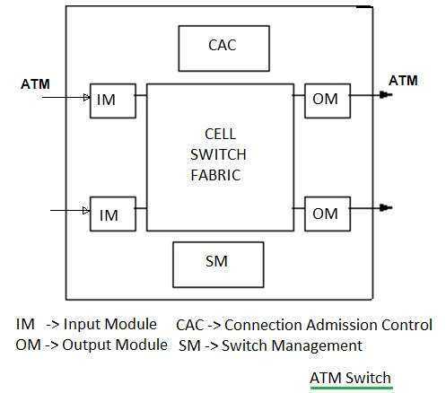
The figure-1 depicts typical modules in an ATM switch.
It s composed of Input modules, output modules, CAC (connection admission control), switch management and cell switch fabric.
VP/VC ATM Switch

ATM switch uses two types of switches viz. VP switch and VP-VC sitch.
Typically, switches connected to users are VPI/VCI switches
while all intermediate switches are only VPI switches
All VPIs and VCIs field have local significance across particular link.
These values are re-arranged or re-mapped as required at the ATM (Asynchronous Transfer Mode) switch.
| Incoming | Outgoing | |||
|---|---|---|---|---|
| VPI | VCI | VPI | VCI | Interface |
| 10 | 122 | 11 | 41 | 1 |
| 121 | 213 | 10 | 158 | 1 |
| 12 | 11 | 211 | 111 | 2 |
| 11 | 151 | 321 | 210 | 2 |
• As shown in figure-2, When cell arrives at the input of ATM switch, it looks up connection
value in local table referred as translation table to determine appropriate
outgoing port for the connection.
• It also assigns new VPI/VCI value of the connection on the same outgoing link.
• The switch re-transmits cell on the outgoing link with appropriate
identifier.
VP ATM Switch

VP switch routes cells based on VPI only. Here VPI values do not change but VCI values
remain same during switching. It uses translation table for switching.
| Incoming | Outgoing | |
|---|---|---|
| VPI | VPI | Interface |
| 22 | 65 | 1 |
| 121 | 99 | 2 |
| 312 | 201 | 1 |
| 11 | 21 | 2 |
Networking related links
What is Bridge What is Router What is Gateway Firewall basics TCP-IP Packet format Difference between OSI and TCPIP layersDifference between TCP UDP Packet Switching vs Message Switching
Translate this page
ARTICLES
T & M section
TERMINOLOGIES
Tutorials
Jobs & Careers
VENDORS
IoT
Online calculators
source codes
APP. NOTES
T & M World Website
Коммутатор Cisco Lightstream ATM Switches
При разработке линии коммутаторов Cisco Lightstream ATM Switches компания – разработчик стремилась достигать лучшего уровня безопасности, а также отказоустойчивого функционирования. Для этого было создано два отсека для мощных блоков питания, которые работают поочередно, в случае возникновения высокой нагрузки в работу включается сразу 2 источника питания.
Коммутаторы Cisco Lightstream ATM Switches созданы специально для тех компаний, где каждая задача, поставленная клиентами должна выполняться в течение сжатых сроков, ведь именно от этого будет зависеть успешность будущих проектов. Пропускная способность в 5 Гбит в секунду гарантирует скоростную передачу данных от центра разработки к системам хранения информации. Между удаленными офисами и филиалами, а также центральным блоком компании должна создаваться быстрая и надежная локальная сеть, позволяющая передавать обработанную информацию на высокой скорости. При использовании таких объектов на территории владения клиент сразу чувствует рост своего предприятия. Мгновенно повышается функция непрерывного роста, для всех компаний, задействованных в области информационных технологий, развитие имеет большое значение, поскольку вместе с ростом увеличивается ресурсоемкость предприятия, количество заказов, а вместе с тем и вложенные инвестиции возвращаются существенно легче.
Линия коммутаторов Cisco Lightstream ATM Switches имеет свой центральный мозг, откуда выполняется автоматизированное управление – это RISC – процессор. Администратор владения способен управлять потоком трафика, делать передачу данных в постоянном или частичном режиме. Когда рабочая среда справляется с нагрузкой и способна пакетами выполнять отправку информации, используется второй вариант передачи трафика. Модульный коммутатор Cisco Lightstream ATM Switches оснащен технологией Cisco LightStream 1010, которая позволяет клиенту быть уверенным в том, что размещенное оборудование не будет работать в режиме нагрузки. Во время большого потока информации коммутаторы Cisco Lightstream ATM Switches выполняют разгрузку в автоматическом режиме. Широкая и полнофункциональная панель управления помогает осуществлять использование модульного коммутатора Cisco Lightstream ATM Switches непосредственно с разработанного интерфейса, что повышает удобство работы с данным продуктом.
Technology Description
This section provides the following ATM technology descriptions:
•
•
•
•
Please see Part 1: Cisco VNEs in this guide for information about which devices support the various technologies.
ATM
ATM is a cell-switching and multiplexing technology that combines the benefits of circuit switching (guaranteed capacity and constant transmission delay) with those of packet switching (flexibility and efficiency for intermittent traffic). It provides data link (Layer 2) services with scalable bandwidth from a few megabits per second (Mb/s) to many gigabits per second (Gb/s), which usually run over SONET/SDH physical (Layer 1) links.
ATM networks consist of ATM switches interconnected by point-to-point ATM links or interfaces and are fundamentally connection oriented, which means that a virtual channel (VC) must be set up across the ATM network prior to any data transfer.
IMA
Inverse Multiplexing over ATM (IMA) involves inverse multiplexing and demultiplexing of ATM cells in a cyclical fashion among physical links grouped to form a higher bandwidth and logical link. The rate of the logical link is approximately the sum of the rate of the physical links in the IMA group. Streams of cells are distributed in a round-robin manner across the multiple T1/E1 links and reassembled at the destination to form the original cell stream. Sequencing is provided using IMA Control Protocol (ICP) cells.
The ATM cell stream received from the ATM layer is distributed on a cell-by-cell basis across the multiple links within the IMA group. At the far end, the receiving IMA unit reassembles the cells from each link on a cell-by-cell basis, recreates the original ATM cell stream, and passes it to the ATM layer.
IP over ATM, Ethernet over ATM (MPoA)
IP over ATM (MPoA 1483R) and Ethernet over ATM (MPoA 1483B) are both implementations of Multi protocol over ATM (MPoA), an ATM Forum standard that provides for routing of legacy protocols (such as IP and Ethernet) over ATM networks.
Based on ATM UNI signaling, and integrating LANE and Next Hop Resolution Protocol (NHRP), MPoA preserves the benefits of LANE while allowing intersubnet, internetwork layer protocol communication over virtual channel connections (VCCs). Unlike LANE, it requires no routers in the data path. MPoA provides a framework for effectively synthesizing bridging and routing with ATM in an environment of diverse protocols, network technologies, and IEEE 802.1 VLANs. MPoA can use routing and bridging information to locate optimal exits from the ATM cloud and allows the physical separation of internetwork layer route calculation and forwarding (virtual routing).
MPoA defines two components—MPoA Clients (MPCs) and MPoA Servers (MPSs)—and the protocols that are required to communicate and receive services. An MPS is a router component, and requires a Next Hop Server (NHS) and interfaces to one or more LAN Emulation Clients (LECs). This MPS route server performs the routing calculations and sends its results to the ATM switches and edge devices, which perform high-speed forwarding of IP datagrams and Ethernet packets.
ATM Cross Connect
ATM networks are based on virtual connections over a high-bandwidth medium. By using cross-connects to interconnect virtual path or virtual channel links, it is possible to build an end-to-end virtual connection.
An ATM cross-connect can be mapped at either of the following levels:
•Virtual path—Cross-connecting two virtual paths maps one Virtual Path Identifier (VPI) on one port to another VPI on the same port or a different port.
•Virtual channel—Cross-connecting at the virtual channel level maps a Virtual Channel Identifier (VCI) of one virtual channel to another VCI on the same virtual path or a different virtual path.
Cross-connect tables translate the VPI and VCI connection identifiers in incoming ATM cells to the VPI and VCI combinations in outgoing ATM cells.


